By Chris Davis, Senior Market Specialist – Electric Utility
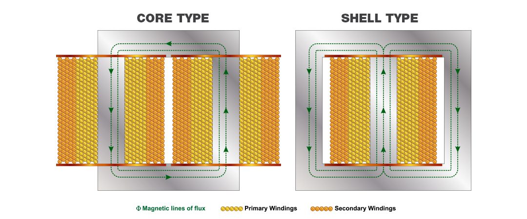
There are two types of core constructions used in oil-filled distribution transformers: closed core design (commonly known as a core type) and shell core design (commonly known as shell type).
Shell type designs
Shell type designs have two cores wound around one coil. The coil is typically wound with two secondary sections and one primary section in a low-high-low winding configuration.
This configuration has part of the low voltage winding next to the core, commonly referred to as the inner low voltage winding. The high voltage winding is then wound around the inner low voltage winding. Finally, the rest of the low voltage winding, referred to as the outer low voltage winding, is wound around high voltage winding.
By having the higher voltage windings closer to the core, leakage distance and impedance are reduced. This also decreases the average length of each high voltage winding, so less material is required for the high voltage windings.
Core type designs
Core type designs have one core wound around two coils. The core design has all the low voltage windings wound closest to the core, with the high voltage windings wound around the low voltage section. This creates a low-high configuration.
In the core type design, the low voltage section is closest to the core to optimize material use. Since the low voltage section carries more current, it uses more material. Having this section closest to the core reduces the average winding length and the amount of material needed.
Coil differences between core type and shell type designs
Where the shell type design has two 120 V sections, the core type design has two 60 V secondary coil sections wound in the inner of each coil, creating four 60 V sections.
Having one 60 V layer from one coil connected to one 60 V layer from the other coil creates interlaced windings. The interlacing of the sections creates the two 120 V sections.
The impact of interlaced windings
When a noninterlaced secondary winding encounters a balanced surge through the secondary terminals, a rapidly changing magnetic field is created across the primary winding.
This induces a very high voltage in the primary winding that causes layer-to-layer voltage stress concentrated at either end of the high voltage winding. This can result in a voltage higher than what the insulation can handle, leading to a layer-to-layer failure.
When an interlaced secondary winding encounters a balanced surge through the secondary terminals, the current flows in opposite directions through the four legs and creates opposite magnetic fields that cancel each other out. The interlacing of the low voltage windings also has a lower inductance between the windings. This limits the voltage on the high voltage windings by allowing fast current flow to ground.
While the standard shell type design doesn’t have interlaced windings, it can be interlaced by splitting the windings and using a four-leg configuration similar to the core type design. This greatly improves the inductance levels of the shell design, but it still doesn’t match the core type design.
The differences in inductance levels between interlaced and noninterlaced windings are greatest in small kVA sizes and decrease as you increase in kVA. For instance, a study conducted by EPRI in 1992 (EPRI TR-000530, Lightning Protection Design Workstation Seminar Notes) showed the inductances of a 10 kVA core to be 17.4 microhenries on an interlaced core type, 18.1 microhenries on an interlaced shell type and 204 microhenries on a noninterlaced shell type.
However, once you get above 50 kVA, the difference in inductance between interlaced and noninterlaced windings is insignificant. This is because the windings have a greater number of volts per turn at higher kVAs.
According to IEEE Transaction on Power Apparatus and Systems, Vol. PAS-101, Issue: 9, single phase transformers with shell-type designs utilizing a non-interlaced 120/240 V rating are most susceptible to failure. Shell type and core type designs with interlaced low voltage windings are least susceptible.
Learn more about core type and shell type designs
Want more information about the differences between core type and shell type designs? Connect with an account manager at your local Border States branch.
Read more
How to Increase the Return on Your Distribution Transformer Investment
How to Choose a Surge Arrester: 4 Factors to Consider
The Benefits of FR3 Fluid vs. Mineral Oil for Distribution Transformers