By Chris Davis, Senior Market Specialist – Electric Utility
Distribution transformers are one of the largest spending categories for an electric utility. As a result, it’s easy to look at the purchase price of a transformer and choose the lowest option.
But while the lowest-priced transformer may mean paying less today, you may pay more in the long run. In this article, we will talk about design features you can add to your specification and protection options that will extend the life of your transformer and save you time.
Table of Contents
- Calculate the true price of a transformer
- The most common cause of transformer damage
- Six features to add to your transformer specifications
- Maximize the life expectancy of your transformers
Calculate the true price of a transformer
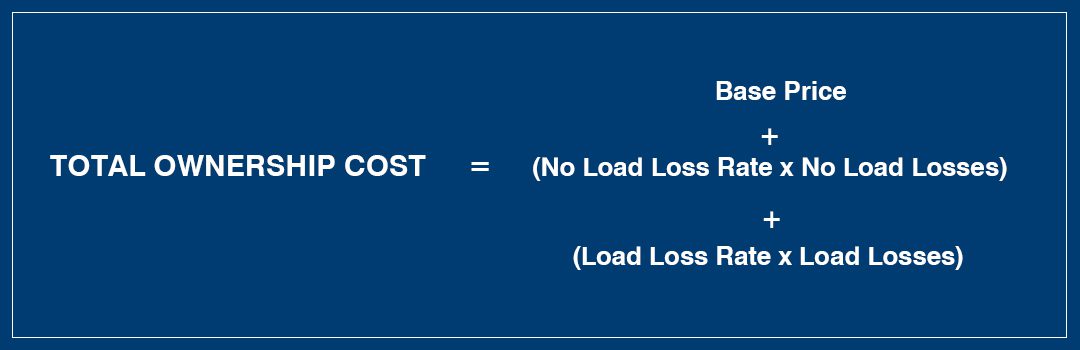
To find the transformer with the best value, you need to understand its total ownership cost. Total ownership cost (TOC) takes transformer losses into consideration instead of just looking at the base price.
Many electric utilities calculate total ownership cost by using a loss evaluation formula. Exact formulas and rates vary from utility to utility, but the most basic and common loss evaluation formula is:
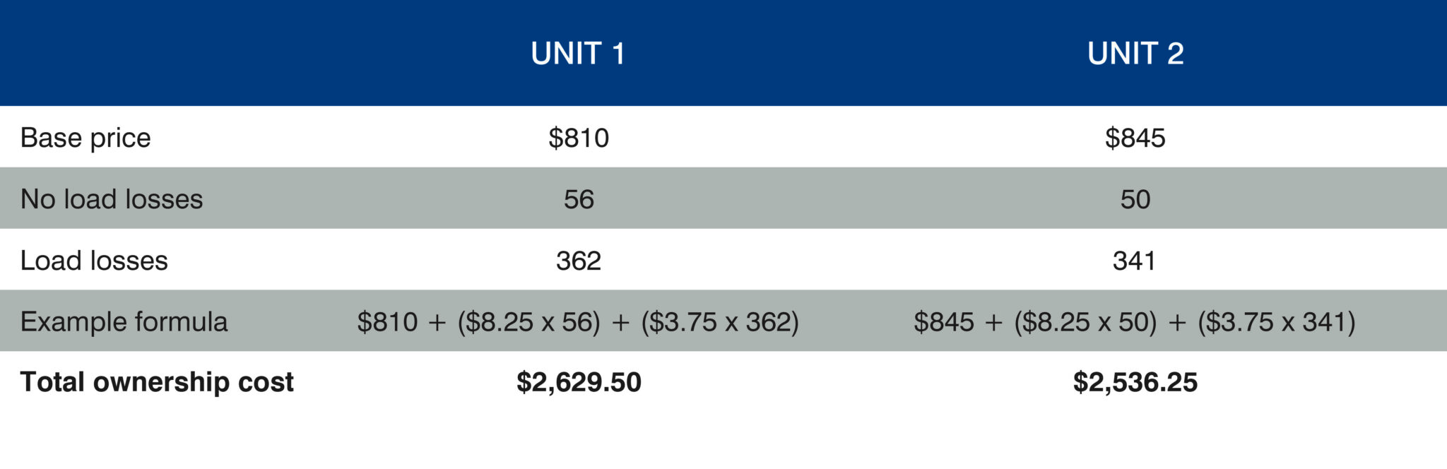
For instance, if you look at the following example of two 25 kVA conventional transformers, you can see how a lower priced transformer can have a higher total cost. For this example, we will use a no load loss rate of $8.25 and a load loss rate of $3.75.
Example: Calculating total ownership cost
Whether you buy off the base price or use a loss evaluation formula, choosing a well-designed and well-protected transformer will extend the life of your transformers. This will save you time and money by not having to send crews out to repair or replace transformers that didn’t meet their life expectancy.
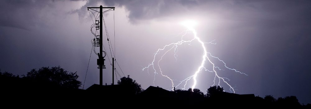
Lightning round: The most common cause of transformer damage
Before we get into how to increase your transformer’s life expectancy, let’s examine one of the main culprits of shortened transformer life: surges.
While surges can be generated by switching, capacitors, inductive device discharges (motors, transformers, etc.) ground faults, outage reductions and loose connections, one of the most common and destructive sources of surges is lightning.
Surges from lightning strikes vary quite a bit, but the average lightning surge is 34 kA, with 28% of lightning strikes being over 50 kA and a voltage rise of 100 to 500 volts in 30 microseconds. According to IEEE C62.41, a typical lightning strike ranges between 20 to 40 kA.
In a few areas of the country, utilities don’t have to worry about lightning. However, this is not the norm. Most utilities need to protect their transformers against lightning surges.
If your state is especially lightning-prone, you may need additional precautions. According to The Weather Channel, Florida had the most lightning events in 2019 with 228 per square mile. It was closely followed by Oklahoma, Missouri, Texas and Louisiana.
Six ways to get the most out of your investment
By choosing a high-quality design, you can increase the return on your transformer investment and decrease maintenance costs. Here are six features to consider when selecting your transformers and protection equipment.
Core design with interlaced windings
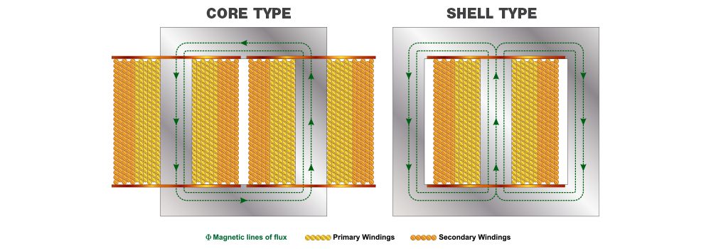
An oil-filled distribution transformer uses one of two core constructions: closed core design (commonly known as a core type) and shell core design (commonly known as a shell type).
While both types use windings to change the voltage on the primary side to another voltage on the secondary side, there are some differences between the two.
Shell Type Design
- Two cores wound around one coil
- Low-high-low winding configuration
- Two 120 V secondary sections
- Standard design has noninterlaced windings
- Windings can be interlaced, but not all manufacturers have it as an option
Core Type Design
- One core wound around two coils
- Low-high winding configuration
- Four 60 V secondary sections
- Standard design has interlaced windings
The main advantage of using interlaced windings is protection from surges coming through the secondary terminals. Interlaced windings accomplish this by splitting the surge into opposite directions and creating opposite magnetic fields that cancel each other out.
Interlaced windings also allow for lower inductance between the windings. This limits the voltage on the high voltage windings and allows a fast current flow to ground.
However, the inductance difference between interlaced and noninterlaced windings decreases as you increase the kVA size. Once you are above 50 kVA, the inductance difference between the two is negligible.
According to a study done by IEEE (Transaction on Power Apparatus and System, Vol. PAS-101, Issue: 9) single-phase transformers with shell type designs using a noninterlaced 120/240 V rating are most susceptible to failure. Shell type and core type designs with interlaced low voltage windings are least susceptible.
For this reason, interlaced windings are recommended on transformers at 50 kVA and below. If you do use noninterlaced windings, you will want to install a secondary arrester.
Learn more about the difference between core and shell type transformers.
Primary and secondary arresters
Arresters are a critical component to protecting your transformers from overvoltage surges. Arresters are designed to take the brunt of the overvoltage and send it to the ground without going through your transformer.
Here are several tips for choosing an arrester:
- Use an overhead distribution arrester for pole-mount transformers and either a parking stand or elbow arrester for pad-mount transformers so you can easily see if the arrester has failed.
- Choose an arrester above your maximum continuous operating voltage (MCOV), but not too far above to limit the maximum discharge voltage.
- Specify the arrester type you want in your transformer spec if you want something other than a normal duty arrester
- Use a secondary arrester to prevent surges in the low voltage side of the transformer.
To learn why we recommend these specific features, see the article How to Choose a Surge Arrester: 4 Factors to Consider.
Conventional transformer with a cutout
A completely self-protected (CSP) pole-mount transformer uses a weak link fuse and secondary breaker inside the transformer for overcurrent protection, while a conventional pole-mount transformer relies on an external cutout.
A conventional transformer with a cutout has several advantages over a CSP transformer.
1. A conventional transformer weighs less.
A CSP transformer has additional weight from the internal components and typically needs more oil.
2. Replacing blown fuses is faster.
The cutout door provides an easy visual indicator to see if the cutout fuse link is blown, and if so, it can quickly be replaced.
With a CSP transformer, crews must test each transformer to see if the weak link fuse is blown. If the fuse is blown, the transformer will need to be taken out of service for the fuse to be replaced.
3. A conventional transformer doesn’t have a secondary breaker.
The breaker linkage tends to have adjustment issues that require line workers to take the lid off the tank and adjust in the field. This issue is commonly caused by movement when transporting the transformers.
Additionally, a secondary breaker causes the CSP transformer to have higher winding losses than a conventional transformer. While the increase in losses on units 50 kVA and below are negligible, they do become more significant on units 75 kVA and above.
4. The interrupting capacity of a cutout is greater.
The weak link fuse in the CSP transformer has an interrupting capacity of only 2,000 amps on a 15 kV system and 1,000 amps on a 25 kV system (interrupting rating may differ, depending on manufacturer). Conversely, a cutout has an interrupting capacity of 10,000 amps on a 15 kV system and 8,000 amps on a 25 kV system.
These differences become a significant issue if the transformer is in an area that could see fault currents above 2,000 amps. If the fault current is high enough, it could cause a catastrophic failure of the transformer.
FR3 fluid

If you want to extend the life of your transformer, FR3 fluid is a wise choice despite the higher upfront cost. The benefits of FR3 compared to mineral oil include:
- Higher flash point and fire point
- Extended insulation paper life
- Increased overload capability
- More environmentally friendly
The one disadvantage of FR3 fluid compared to mineral oil is that it has a higher pour point of -6° F, compared to mineral oil’s -40° F. However, the heat generated from the transformer is generally enough to keep fluid temperatures above the pour point. Even if the temperature goes below the pour point and the FR3 fluid starts to gel, it retains its dielectric strength to at least -58 °F.
We’ve had a couple customers in cold, high elevation regions experience issues with FR3 fluid gelling after extended periods of temperatures well below the pour point and minimal load. However, we also have several customers in areas that see temperatures regularly below the pour point that have never had an issue with FR3 fluid gelling.
Learn more about the benefits of FR3 fluid over mineral oil.
Paint finish and quality
A good paint finish isn’t something that you can add to a transformer spec, but it is important to pay attention to because rust can significantly reduce the life of a transformer.
While no manufacturer is perfect and there will be paint damage from being handled and sitting in the elements, it is important to monitor if you have poor paint quality on a consistent basis from a manufacturer. If a manufacturer consistently has poor paint quality and rusts easily, you should reconsider buying from that manufacturer.
If you have transformers in a highly corrosive environment, such as near an ocean, an industrial plant or a road that is heavily salted during the winter, it may be a good idea to switch from mild steel to stainless steel. There will be a premium for stainless steel, but it could be worth the extra upfront investment.
Bushing wells with replaceable studs
Replaceable studs in the primary bushing wells won’t extend the life of a transformer, but it will save you time if you break the stud while inserting the bushing.
If you don’t have replaceable studs, you will need to drain the transformer and replace the well. With a replaceable stud, you just need to unscrew the old stud and put in the new one. This will prevent the transformer from needing to be taken out of service.
Maximize the life expectancy of your transformers
Transformers make up a significant portion of an electric utility’s total spend, so getting the most out of your investment is important.
To recap, these factors can extend the life of your transformers and save you time:
- Interlaced windings
- Primary and secondary surge arresters
- Conventional transformers with cutouts
- FR3 fluid
- Paint finish and quality
- Replaceable bushing well studs
To learn more or discuss other transformer options, such as tap changers, load break switches, stenciling and more, connect with an account manager at a Border States branch near you. They can help you find the solution that provides the best value for your service area.
Read more
Core Type vs. Shell Type Distribution Transformers
How to Choose a Surge Arrester: 4 Factors to Consider
The Benefits of FR3 Fluid vs. Mineral Oil for Distribution Transformers