 Keeping industrial motors running at peak performance is becoming increasingly complex, which is why it’s important for facility operators to know how to conduct a proper motor failure root cause analysis.
This involves understanding the mechanical and electrical vulnerabilities of motors. Winding insulation breakdown and bearing wear are the two most common culprits.
Having the right knowledge can mean the difference between costly downtime and improved asset uptime. Keep reading to learn about the most common causes of motor failure.
Transient voltage
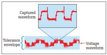
 Transient voltage can come from multiple sources such as adjacent loads turning on or off, power factor correction capacitor banks or electrical storm interruption.
This phenomenon is notorious for causing erosion in motor windings. When seeking the source of transient voltage, be aware there might not be direct equipment damage, but overall operations could be affected.
Voltage imbalance
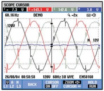
 Three-phase distribution systems are often found serving single-phase loads. An imbalance in load distribution can in turn cause imbalance across all phases.
Potential faults may lie in the motor’s cabling, terminations or windings, causing stress to each phase circuit. Simply put, all three voltage phases should always have the same magnitude.
Harmonic distortion
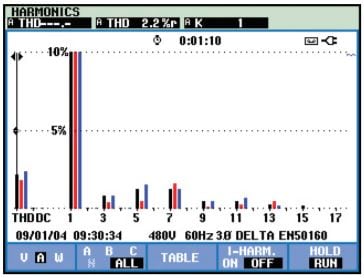 Harmonics are sources of high frequency AC voltages or currents supplying unwanted energy to motor windings, ultimately leading to internal energy losses that dissipate in the form of heat and deteriorate the insulation capability of windings.
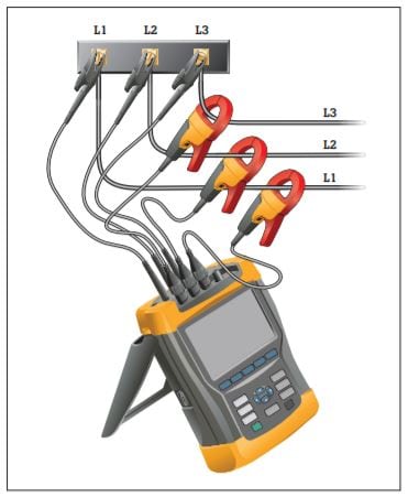
Try using a power quality analyzer to monitor electrical current levels and temperatures, making sure transformers are not overstressed.
Reflections on drive output PWM signals
 Variable frequency drives use pulse width modulation (PWM) to control output voltage and frequency to a motor. Reflections are generated when there is an impedance mismatch between the source and load.
Impedance mismatches can occur because of improper installation, improper component selection or equipment degradation. In a motor drive circuit, the peak of the reflection could be as high as the DC bus voltage level.
Sigma current
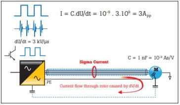 Sigma current essentially involves stray currents that circulate in a system. They’re created as a result of the signal frequency, voltage level, capacitance and inductance that is found in conductors. These circulating currents can cause nuisance tripping or excess heat in windings.
Found in motor cabling, sigma current reflects the sum of the three currents. In a perfect situation, the sum would equal zero. (The return current from the drive would be equal to the current to the drive.)
Operational overload
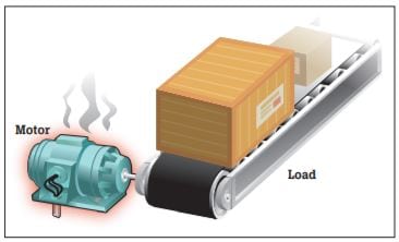 Fairly self-explanatory, motor overload occurs when there is excessive current draw, insufficient torque and overheating. Individual components like bearings and windings might continue to work fine, but the motor will continue to run hot.
Misalignment
 Misalignment occurs when the motor drive shaft is not in correct alignment with the load or the component that couples the motor to the load is misaligned.
Many professionals mistakenly believe a flexible coupling compensates for misalignment, but even with a flexible coupling, a misaligned shaft will transmit damaging cyclical forces along the shaft and into the motor, leading to excess wear on the motor. Additionally, misalignment might feed vibration into both the load and the motor drive shaft.
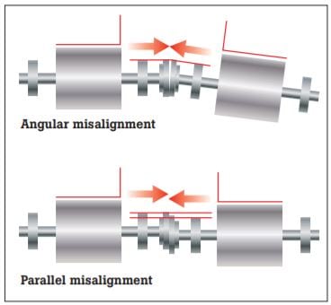
There are a few types of misalignment to be aware of:
- Angular misalignment: Shaft centerlines intersect but are not parallel.
- Parallel misalignment: Shaft centerlines are parallel but not concentric.
- Compound misalignment: This is a combination of parallel and angular misalignment. (Almost all misalignment is compound misalignment.)
Shaft imbalance
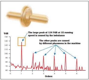 This type of imbalance involves a rotating part where the center of mass does not lie on the axis of rotation. In other words, there is a “heavy spot” somewhere on the rotor.
You can never completely eliminate motor imbalance, but you can identify when it’s out of normal range. Imbalance can be caused by numerous factors, including:
- Dirt accumulation
- Missing balance weights
- Manufacturing variations
- Uneven mass in motor windings
A vibration tester or analyzer can help you determine whether a rotating machine is in balance.
Shaft looseness
 Shaft looseness occurs when there is excessive clearance between parts.
- Rotating looseness is caused by excessive clearance between rotating and stationary element, such as in a bearing.
- Nonrotating looseness happens between two normally stationary parts, such as a bearing housing and a machine.
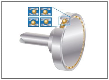
Bearing wear
 A failed bearing has increased drag, emits more heat and has lower efficiency. Bearing failure can be caused by several things:
- A heavier load than designed for
- Inadequate or incorrect lubrication
- Ineffective bearing sealing
- Shaft misalignment
- Incorrect fit
- Normal wear
- Induced shaft voltages
Soft foot
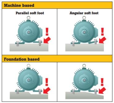 Soft foot refers to a condition in which the mounting feet of a motor or driven component are not even or the mounting surface upon which the mounting feet sit is not even. There are two kinds of soft foot:
- Parallel soft foot: When one of the mounting feet sits higher than the other three.
- Angular soft foot: When one of the mounting feet is not parallel or “normal” to the mounting surface.
Pipe strain
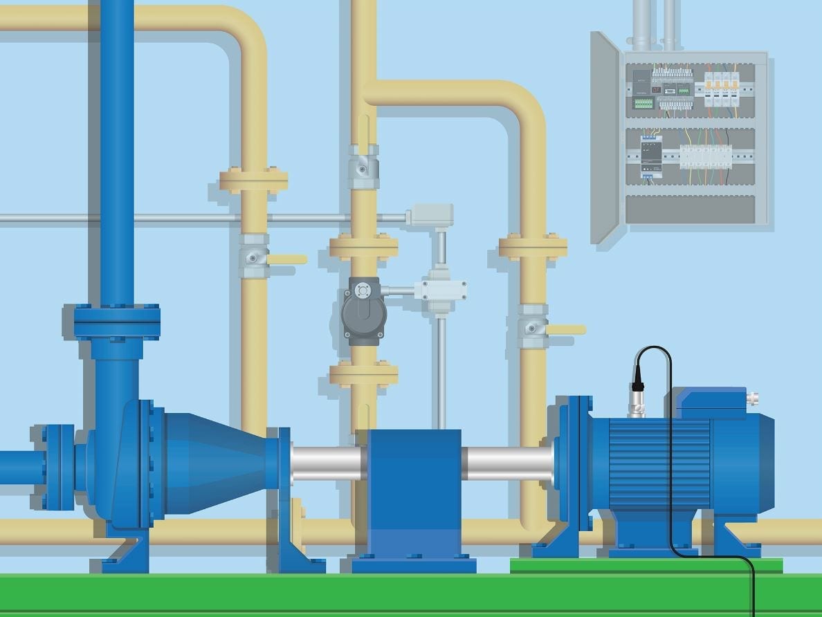
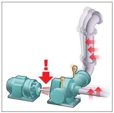 Pipe strain refers to the condition in which equipment strains transfer backward onto the motor and drive to cause misalignment. The most common example of this is in simple motor-pump combinations.
It’s important to check machine alignment more than just at the time of installation.
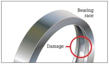
Shaft voltage
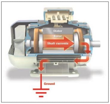 When motor shaft voltages exceed the insulating capability of the bearing grease, flashover currents to the outer bearing will occur, thereby causing pitting and grooving to the bearing races.
The first signs of this problem will be noise and overheating as the bearings begin to lose their original shape and metal fragments mix with the grease and increase bearing friction. This can lead to bearing destruction within a few months, an expensive problem both in terms of motor repair and downtime.
A carbon brush probe attachment allows you to measure shaft voltage while a motor is rotating.
Strategies for success: Motor failure root cause analysis
Equipment failure can result in high monetary losses from parts replacement and equipment downtime. Arming maintenance engineers and technicians with the right knowledge, prioritizing workload and managing preventative maintenance to monitor equipment and troubleshoot problems can help avoid system failures.
There are four key strategies you can undertake to prevent premature failures in motor drive and rotating component:
- Document operating conditions, machine specifications and performance tolerance ranges.
- Capture critical measurements at installation, before and after maintenance and on a routine basis.
This blog post was drafted in partnership with Fluke Corporation. Read Fluke’s original article, “13 common causes of motor failure.”
Related posts
Measure voltage without test leads with Fluke’s T6 Electrical Tester