 Heat is often an early symptom of equipment damage or malfunction, which is why it’s important to utilize infrared preventive maintenance to check the temperature of critical equipment and quickly identify unusual readings.
Avoid unplanned downtime
By monitoring equipment performance and scheduling maintenance when needed, facilities reduce the likelihood of unplanned downtime due to equipment failure. They also spend less on reactive maintenance fees and equipment repair costs, extending the lifespan of machine assets.
Infrared preventive maintenance isn’t meant to create excessive maintenance efforts, but rather to transition maintenance resources away from emergency repairs and toward scheduled inspections of key equipment. Inspections take less time than repairs, especially if done with a thermal imager.
Save money
Studies by the Federal Energy Management Program (FEMP), estimate a properly working preventive maintenance program can lead to 30-40 percent savings. Other independent surveys show that, on average, sustaining an industrial preventive maintenance program results in:
- Return on investment: 10 times
- Reduction in maintenance costs: 25 percent to 30 percent
- Elimination of breakdowns: 70 percent to 75 percent
- Reduction in downtime: 35 percent to 45 percent
- Increase in production: 20 percent to 25 percent
Integrating thermography into preventive maintenance
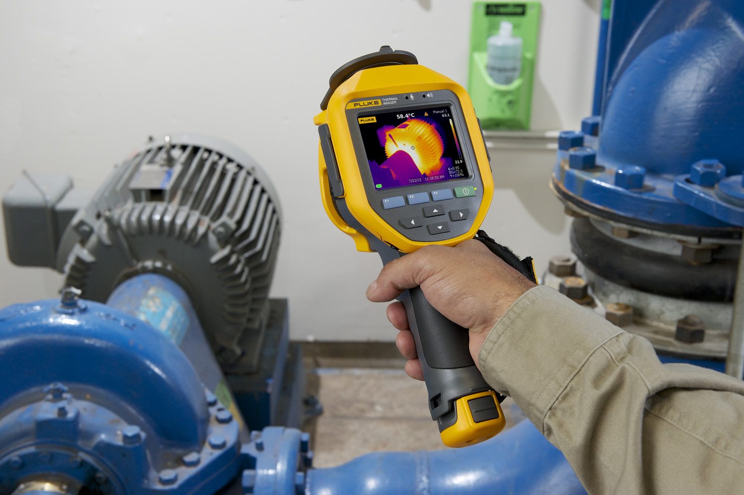
Infrared cameras are often the first inspection tool a technician thinks to use as part of their preventive maintenance program. They can swiftly measure and compare heat signatures for all equipment on the inspection route – without interrupting operations.
If the temperature is noticeably different from previous readings, facilities can then use other maintenance technologies –vibration, motor circuit analysis, airborne ultrasound and lube analysis – to investigate the source of the problem, and its solution.
For best results, integrate your maintenance technologies into the same computer system. Once the infrared data is correlated with data from other technologies, the actual operating condition of all assets can be reported in an integrated format.
Applications
- Monitor and measure bearing temperatures in large motors or other rotating equipment.
- Identify “hot spots” in electrical equipment.
- Identify leaks in sealed vessels.
- Find faulty insulation in process pipes or other insulated processes.
- Find faulty terminations in high power electrical circuits.
- Locate overloaded circuit breakers in a power panel.
- Identify fuses at or near their current rated capacity.
- Identify problems in electrical switch gear.
- Capture process temperature readings.
Inspection process
- Use existing lists of equipment from a computerized maintenance management system (CMMS) or another inventory tool.
- Eliminate items that aren’t well suited for infrared measurement.
- Review maintenance and production records. Prioritize key equipment that is prone to failure or often causes production bottlenecks.
- Use a database or spreadsheet to group the critical equipment together, either by area or function, into roughly two- or three-hour inspection blocks.
- Use your infrared camera to capture baseline images of each piece of critical equipment. (Note: on some pieces of equipment, you may want to regularly capture multiple thermal images of key components or subsystems.)
- Download the baseline images into software and document your route with location descriptions, inspection notes, emissivity and RTC levels and alarm levels, if appropriate.
- When the next inspection is due, if your imager supports uploading, simply load the previous inspection images onto the camera and follow the onscreen prompts.
Measurement guidelines for infrared preventive maintenance
To capture the best thermal images, follow these best practices:
- Verify the target system is operating at a minimum 40 percent of load (lighter loads don’t produce much heat, making it hard to detect problems).
- Get close to your target and don’t “shoot” through doors, especially not through glass. When safety procedures allow, electrical enclosures must be opened, or infrared windows or viewports utilized.
- Account for wind and air currents. These powerful convective forces cool the abnormal hot spots, making it challenging to detect abnormalities.
- Account for ambient air temperatures, especially outdoors. The sun can heat up equipment, while cold weather can mask the effects of overheating components.
- Not all problems are hot! Blown fuses and restricted flow in cooling systems are just two examples of situations where a problem is indicated by a cooler-than-normal signature. In other cases, a cold component is abnormal due to the current being shunted away from the high-resistance connection. Thermographers must understand how a machine works and what its heat-related failure signatures are.
- Consider sources for reflective infrared radiation. Items that have shiny reflective surfaces and are emissive will reflect infrared energy from other nearby objects, including the sun. This can interfere with target temperature measurement and image capture.
- Unpainted metals are difficult to measure. To improve measurement accuracy and repeatability, consider attaching “targets” (paper stickers, electrical tape, painted spots, etc.) to such components.
- Accumulate both numeric temperatures and thermal images, to facilitate long-term data analysis. Temperature trends will show you where to investigate more and where inspections can be less frequent.
- Once you have a database of baseline images, associate an alarm temperature with each one. Upload the most recent version onto your camera before each inspection. If the alarm goes off when you take the new measurement, that indicates a significant change in temperature that needs to be investigated.
Example 1: Inspecting motor bearings
When checking motor bearings, start with a newly commissioned and freshly lubricated motor and take a snapshot of the housing while the motor is running. Use this image as a baseline.
As the motor and its lubrication ages, the bearings become worn and heat-producing friction develops in the motor bearing, causing the outside of the bearing housing to heat up. Take additional thermal images at regular intervals, comparing them to the baseline to analyze the motor’s condition.
When the thermal images indicate an overheating bearing, generate a maintenance order to replace or lubricate the bearing housing.
Example 2: Spotting leaky seals and gaskets
Finding leaks in sealed vessels is easy with thermal imagers. Most leaks develop in or around a gasket or seal. Less often, corrosion will cause a weakness to develop and rupture the vessel.
Either way, an infrared imager can diagnose the problem. To find a leaky gasket or seal, scan the imager along the seal, looking for thermal anomalies. A significant change in temperature along the seal or gasket indicates a loss of heat or cold, pointing to a failure.
This article was drafted in partnership with Fluke. Read Fluke’s original article, “Infrared cameras, on the front line for preventive maintenance.”